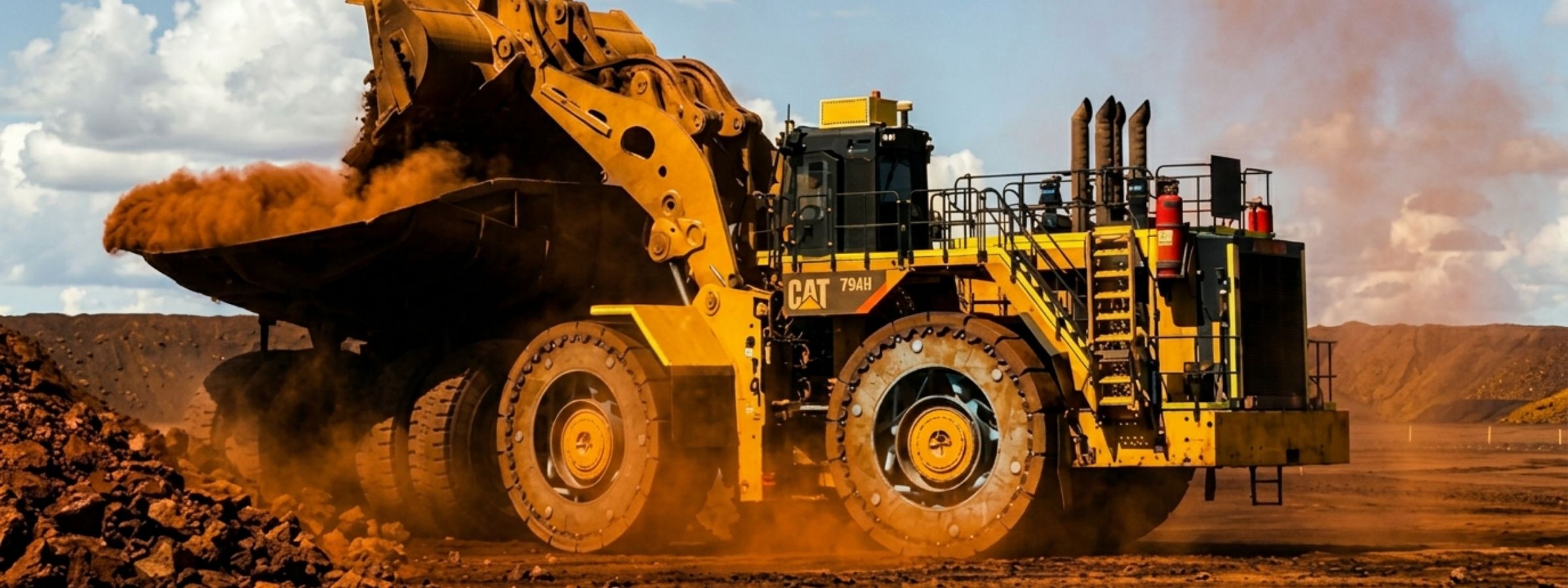
A steel wheel with the suspension built inside it — replacing the pneumatic OTR tyre entirely. No pressurised gas volume. No blowout failure mode. No whole-tyre replacement.
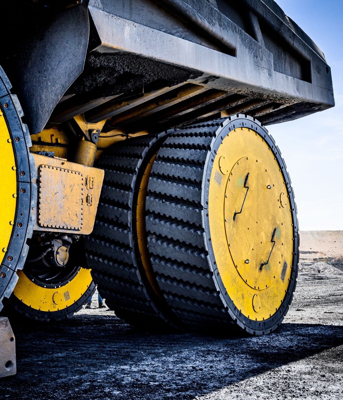
The Air Suspension Wheel (ASW) is a steel wheel with an integrated air-cylinder and damper suspension system. It replaces the conventional pneumatic tyre and tyre-plus-rim assembly as a single bolt-on unit for validated configurations, using the OEM hub interface where compatibility has been confirmed.
The suspension — the function pneumatic tyres have always served alongside containment — is now carried by engineered steel cylinders and dampers inside the wheel body. Air cylinders absorb impact and provide compliance. Load is managed, not assumed.
The ground interface is a bolt-on tread segment ring — replaced as individual segments, without removing the wheel from the machine. The failure mode of a conventional pneumatic blowout is removed at source: there is no large pressurised gas volume in the ASW.
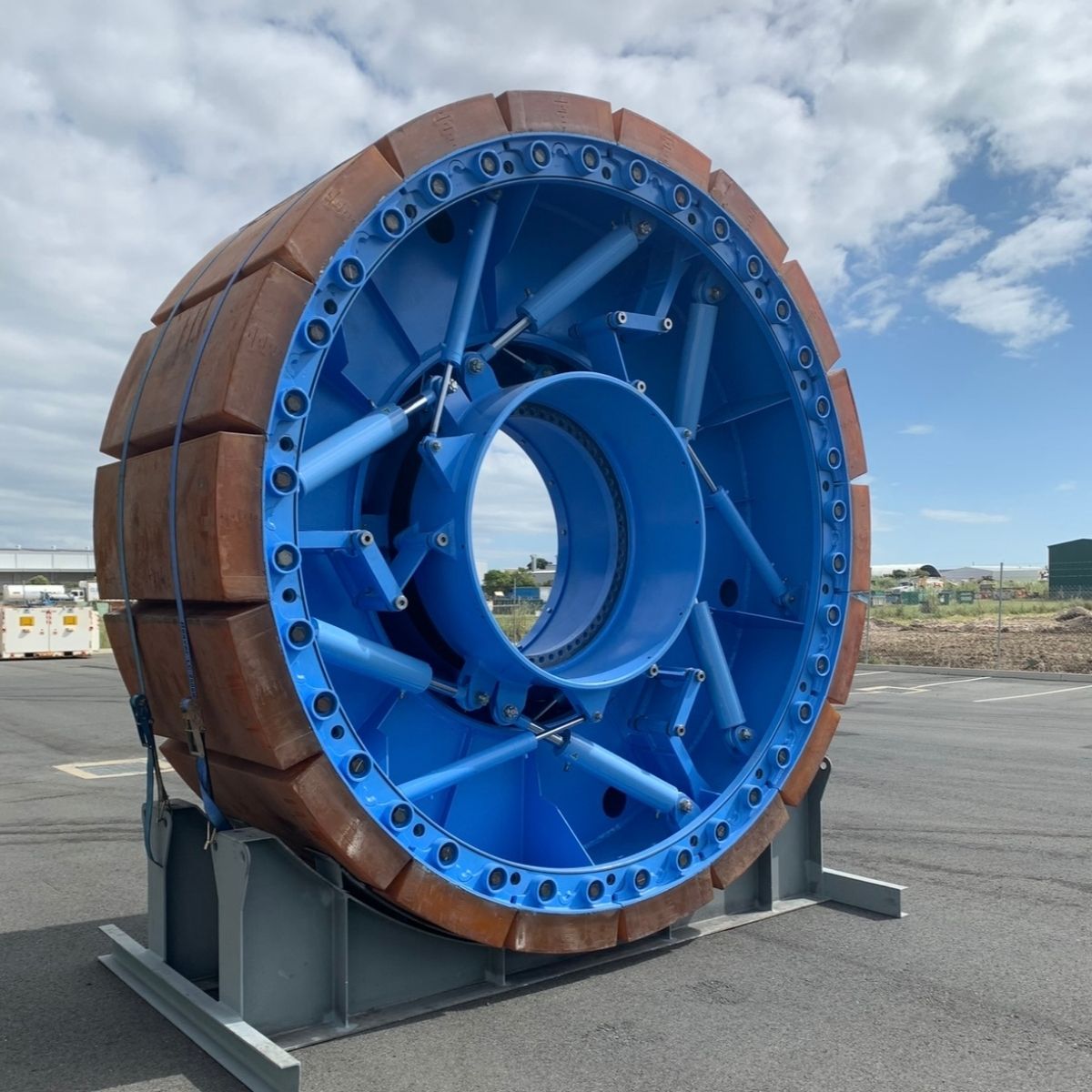
Four integrated systems replace the function of a conventional pneumatic OTR tyre.
A precision-engineered steel outer shell replaces the tyre carcass and carries the structural load of the haul cycle without relying on rubber deformation, heat buildup, or tyre pressure to maintain load-bearing capability.
Rather than relying on tyre deformation and air pressure to provide compliance, the ASW utilises an integrated suspension mechanism with adjustable damping characteristics. This allows the system to control impact energy, manage dynamic loads, and provide predictable load attenuation before forces are transmitted into the axle, frame, and vehicle suspension.
The ground interface is a set of bolted tread segments around the outer circumference. Worn segments are replaced one at a time — without removing the wheel from the axle — during scheduled maintenance windows, not emergency shutdowns.
The ASW mounts to the existing wheel hub using the same bolt pattern and interface geometry as the original equipment specification. No structural modification to the machine is required for installation.
Dedicated structural members provide the only constraint in the lateral plane between drum and rim. They carry lateral loads, define lateral stiffness, and maintain alignment between rotating components — replacing the continuous lateral load-carrying behaviour of a tyre carcass with discrete engineered members.
OTR tyre safety management is an industry dedicated to managing a fundamental failure mode: catastrophic stored energy release. Tyre pressure monitoring, exclusion zones, deflation procedures, and emergency protocols exist because the failure is real and severe.
The ASW contains no large-volume pressurised gas envelope. The conventional pneumatic tyre blowout failure mode is therefore not present in the ASW architecture, reducing the need to manage that specific high-energy failure mode while leaving other equipment, operating, and maintenance risks to be controlled through normal site systems.
Safety performance data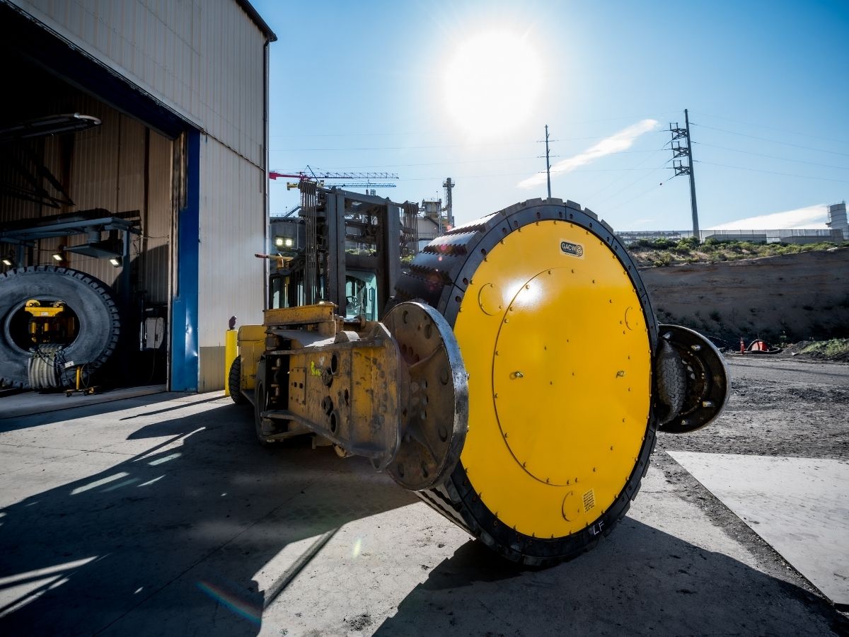
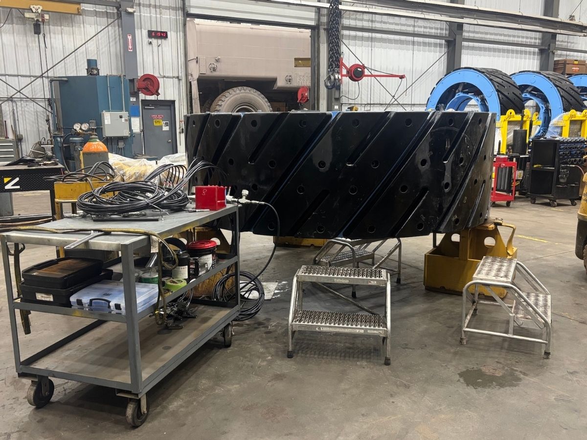
Conventional tyre replacement requires full shutdown, jack operation, bead-breaking, dismounting, disposal logistics, and reinstallation — for the entire tyre carcass. The ASW eliminates this.
When tread wears, individual segments — a fraction of the wheel assembly by mass and cost — are removed and replaced on the machine, without removing the wheel from the axle. Tyre-specific maintenance activities are replaced by component servicing on a scheduled, predictable cycle.
Large OTR mining tyres are manufactured by a small number of suppliers globally. Demand is inelastic and concentrated in commodity-cycle peaks. When supply is constrained — and it has been, repeatedly — fleet operations are directly impacted.
The ASW carries no tyre supply exposure. Components — tread segments, cylinders, dampers — are engineered and supplied by GACWheels through the Wheels-as-a-Service model, with inventory managed to your fleet size and operating schedule.

Specifications indicative. Final configuration validated per site application. Contact GACWheels for formal specification review.
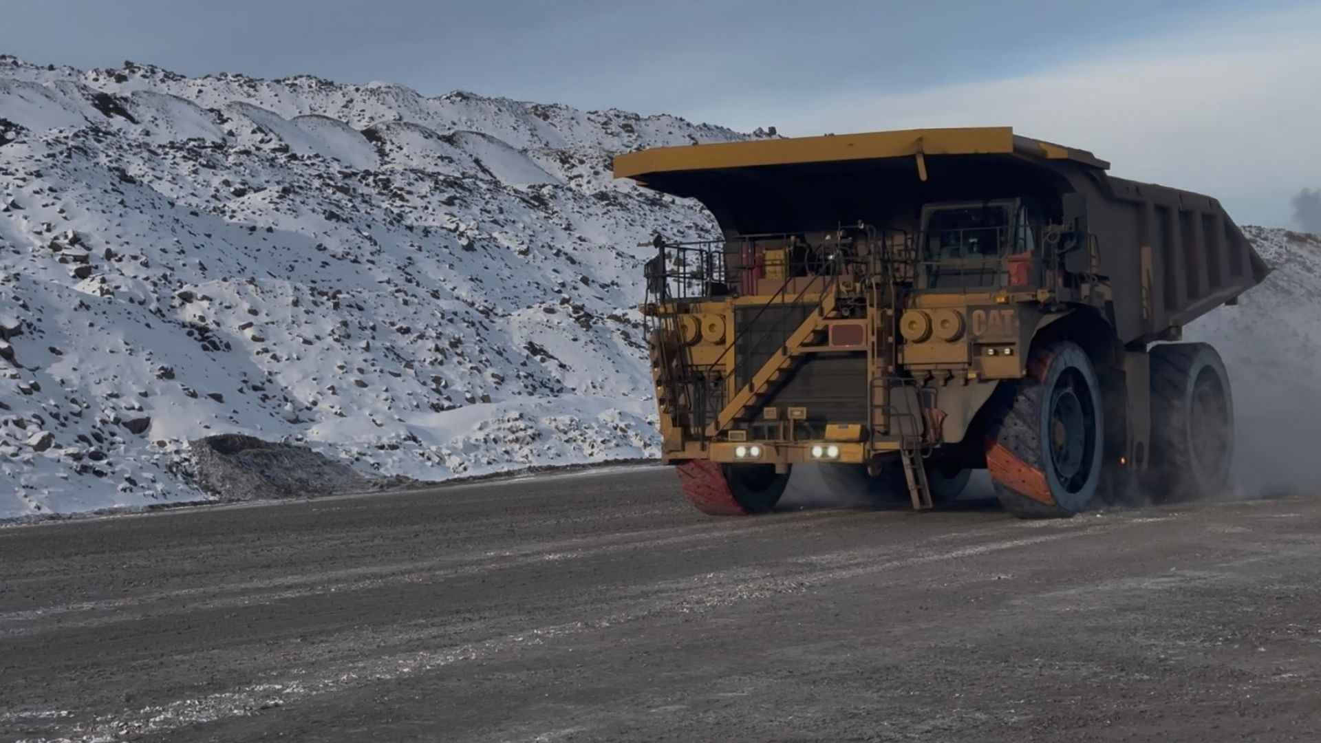
The ASW has been validated under real-world mining duty cycles — including fully loaded haul cycles, high-frequency manoeuvring, and worst-case static turning scenarios — with instrumentation capturing vibration, load response, and structural behaviour.
The system has been evaluated under repetitive high-cycle operations and ground impact conditions using strain gauging, accelerometry, and telemetry — across environmental ranges from −40°C to +50°C.
GACWheels' patent portfolio includes more than 120 issued patents and related rights covering aspects of the ASW system, including wheel architecture, air-cylinder and damper suspension elements, tread segment design and attachment, manufacturing methods, and operational configurations in multiple jurisdictions.
This IP portfolio represents a defensible moat around the core technology and reflects a decade of engineering development, field validation, and iterative refinement — from prototype through commercial-scale deployment.
Full comparative analysis — ASW vs. pneumatic tyres across safety, cost, operations, environment, and supply chain resilience.
Field data from 9+ years of operational testing — cost savings, downtime reduction, and maintenance performance from real fleet deployments.
Bring your application — machine type, site conditions, payload, haul profile. A GACWheels engineer will walk through compatibility and the case for your fleet.